is a machine that rotates a sample that
separates components or phases of the sample by centrifugal force, it is
composed of a rotor, a sample holder, an LCD screen and command control, where
the emergency button and start button are located of the cycle on the other
hand has a keyboard in which the RPM are entered and the time that the user
wants it to last.
The LCD shows the RPM generated in the process of centrifugation and also gives warning that the lid is open, the rotor is off and the emergency stop, therefore are made by arduino programming alarms with line sensors explained later.
Programming code:
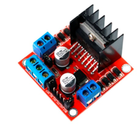 |
| Figure 1,L298n module |
It was used a L298N module to control motor
velocity with the PWM Arduinos module. The L298n has three inputs, both of them
are the motor direction called in1 and in2, one of the must be in a High level
to move the motor, if the two inputs are on HIGH, the motor won´t move and we
could cause a damage in in the module or the Arduino. The other INPUT is the
Enable, it has the function to control the motor velocity with the PWM, with
the Arduino’s function “analogWrite” we can send a pulse between 0 and 255, where
255 represent the highest velocity in the module and 0 is the lowest velocity.
To send this pulse with the keypad, we have to make a linear regression between
the bandwidth pulse and the rpm required, the first point is p1(90,1000) and
the second point is p2(255,500) setting a minim rpm value of 1000rpm and a
maximum of 5000 rpm.
 |
Figure 2,linear regression
|
The main equation
is represented in the last figure, but we want to predict send the pulse value
to the module enable knowing the rpm’s values, for that reason, we calculate x
in the equation: where numero is the rpm value and velocidad is the pulse value.
where numero is the rpm value and velocidad is the pulse value. |
Figure 3,controling rpms
|
In this code, we activate one input of the
module, and send the pulse with the function analogWrite in the third Arduino’s
pin.
To
compare the rpms values are correct, we used a encoder that detects the rotor’s
holes sending a pulse to the Arduino, the centrifuge rotor had 2 holes.
 |
Figure 4, rpms code
|
When the
encoder send a LOW level, it is indicating a hole, when it happens, a counter
increases each 10 ms, to
Know the real value during the time configured,
we used the next equation:
ALARM
Alarm for the lid
It is done with a
line sensor located in a corner of the box where to find below cover this sends
a 5 and performs the normal cycle of sample centrifugation, but to find the lid
open sends a 0 to the arduino where q alert is displayed on the LCD EU cover is
open and the centrifugation process stops until the lid is closed.
The designed
centrifuge allows to put two pairs if the rotor is decalibrated it can not
initiate the centrifugation process since if the sample pair is not located in
the sample holder it can not start the cycle therefore an alarm was made with
the line sensors located on the side of the sample at the bottom.
If sensor1 is equal to
LOW and sensor is equal to LOW or sensor1 it is equal HIGH and sensor2 equal to
HIGH that performs all process for centrifugation, so that if sensor1 = LOW and
sensor2 = HIGH it will not do anything until the rotor is
calibrated .
As you can see in the next video:
Emergency stop
This was done with a button where if it was equal to LOW this could perform the normal centrifugation process, but if the user turned on the button it would stop the rotor stopping the sample holder, showing the EMERGENCY alert on the LCD until the student turned off said button.As you can see in the next video:
RESULT
As you can see as a result, the same RPM entered by the student were obtained where they were shown in LCD as you can see in the following picture:
 |
| figure 5. RPM |
No hay comentarios:
Publicar un comentario